Page 1 of 3

Quick Charge Mod - CH4D3M0

Posted: Fri Apr 22, 2022 8:48 pm
by Anti_Climax
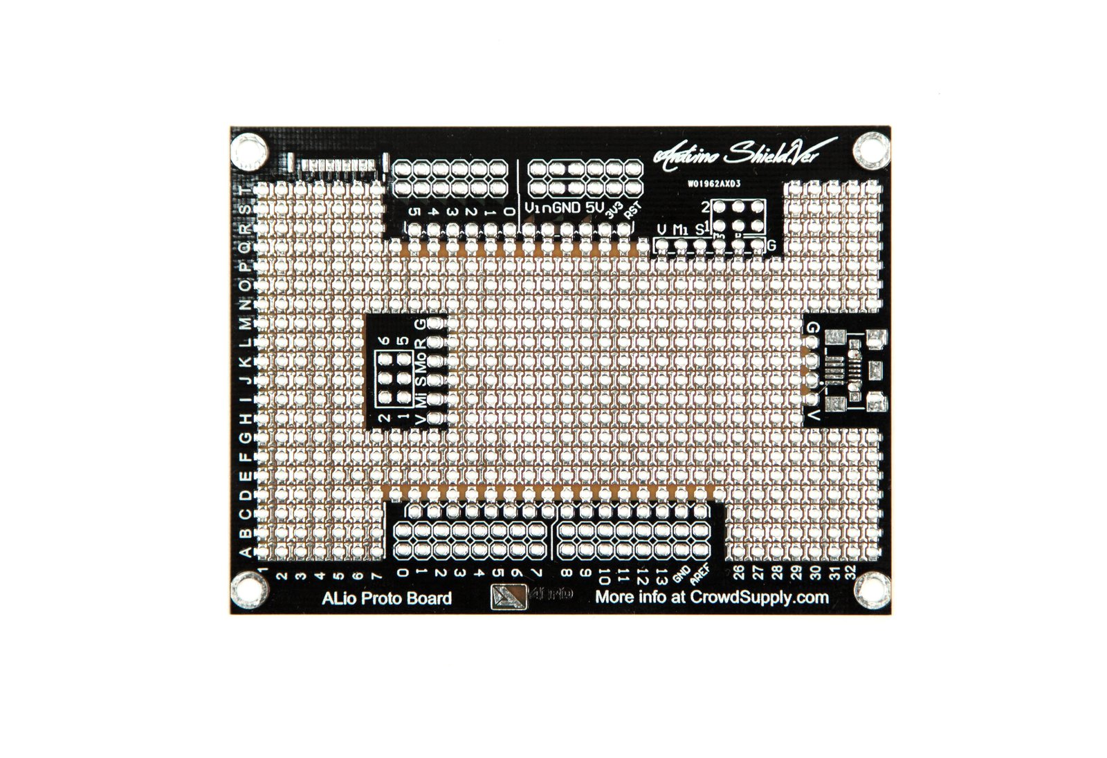
Since taking possession of the CHAdeMO quick charge hardware from Sefs, I've posted most of the code to Github (https://github.com/truss-cpi/FFE-CHAdeMO) along with some other data. In parallel I've designed a "shield" for the EVTV CANDue that should contain every low voltage thing needed to manage a CHAdeMO connection. Combine that CANDue and Shield with the port, contactors and HV wiring, and you have everything you need.

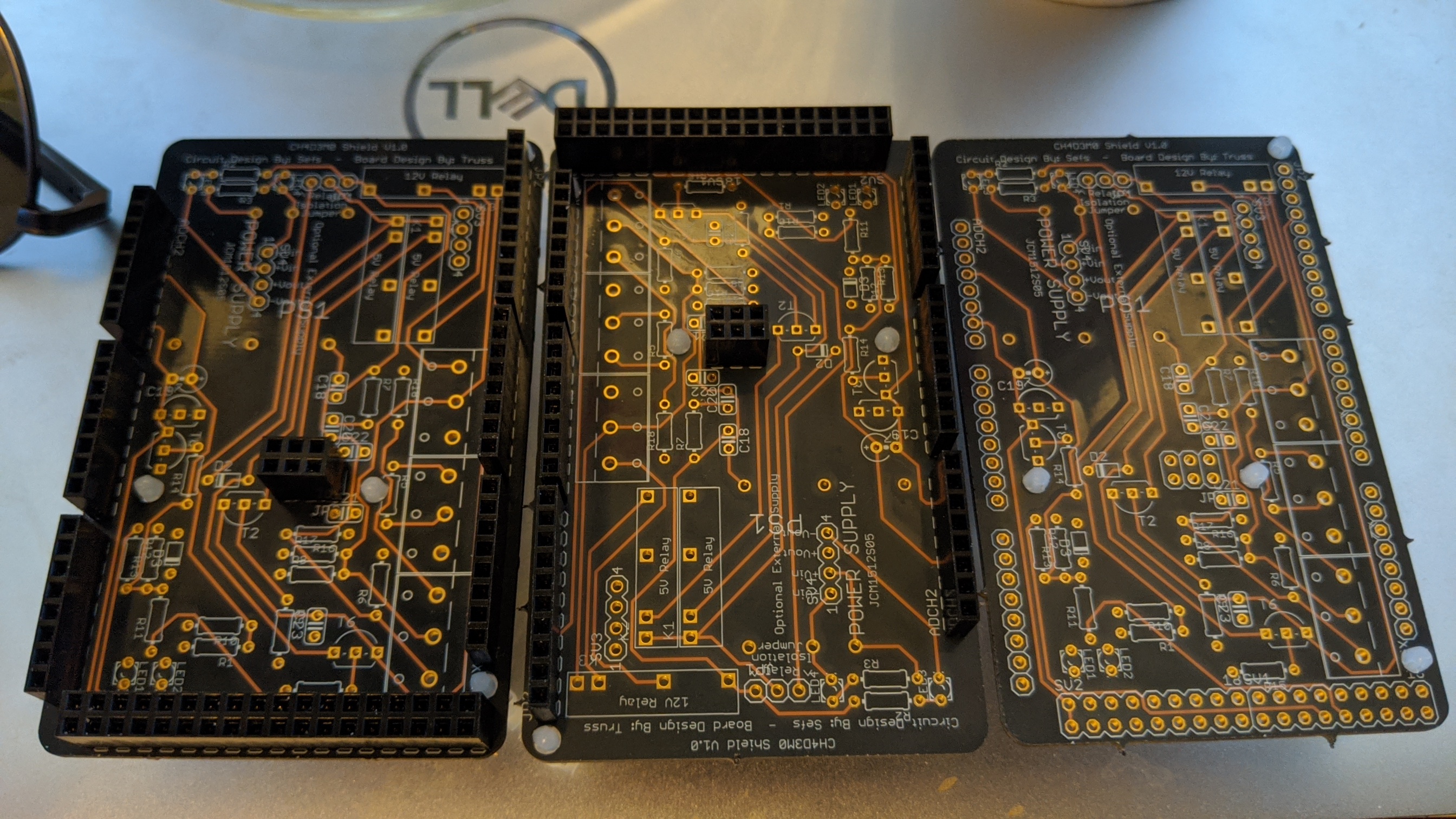
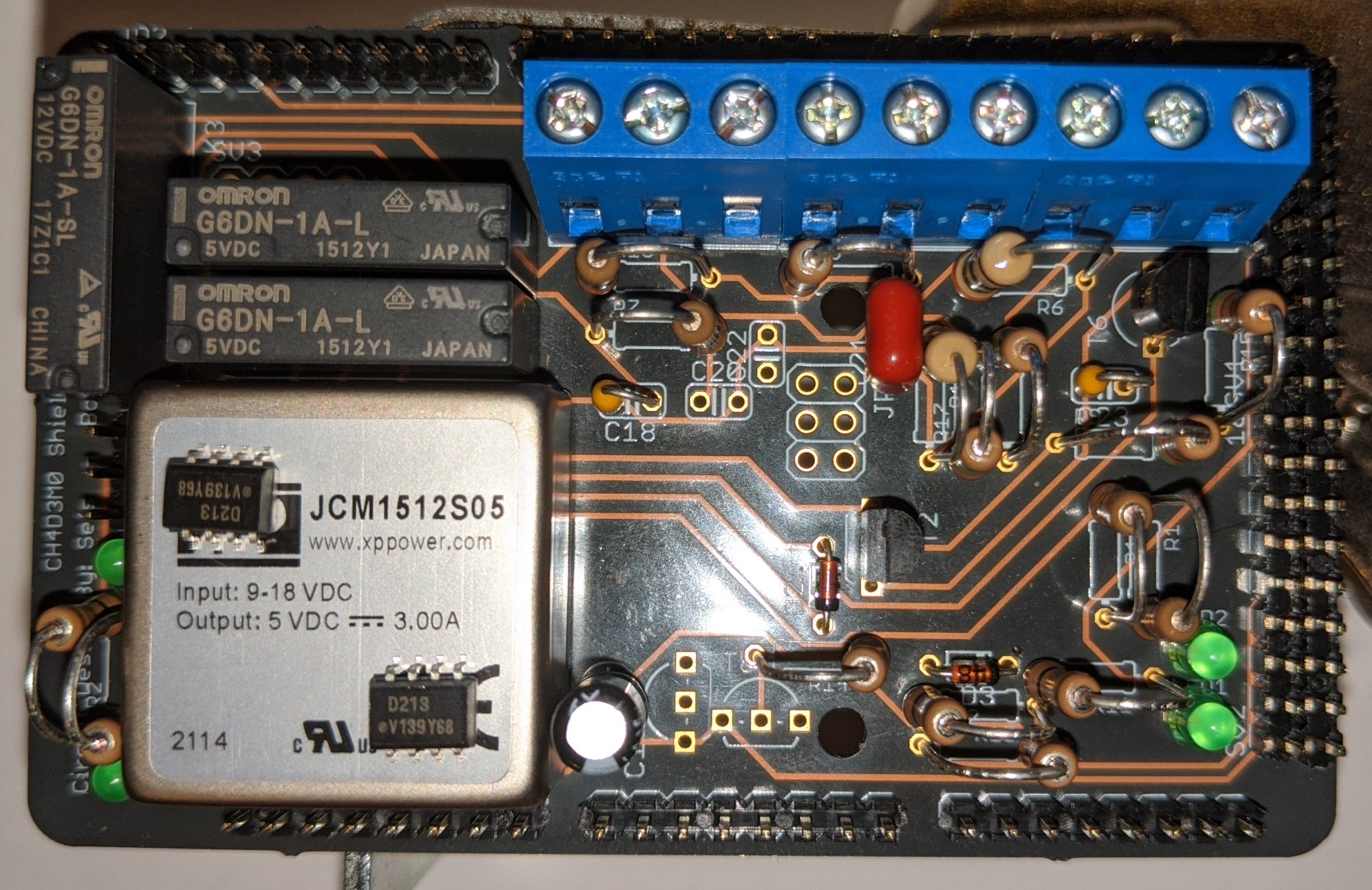
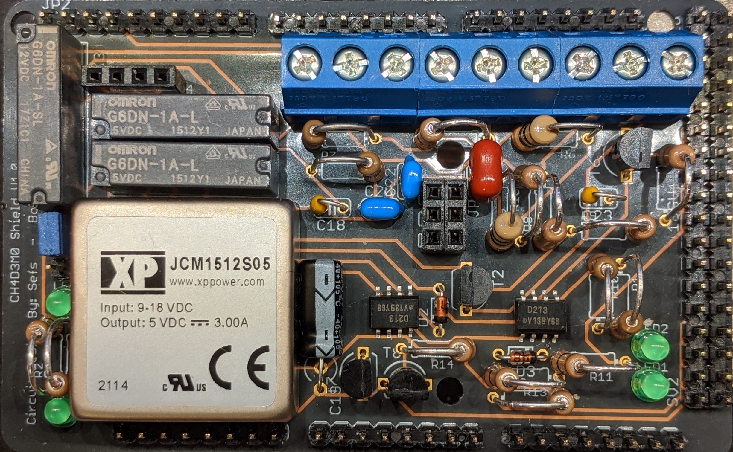
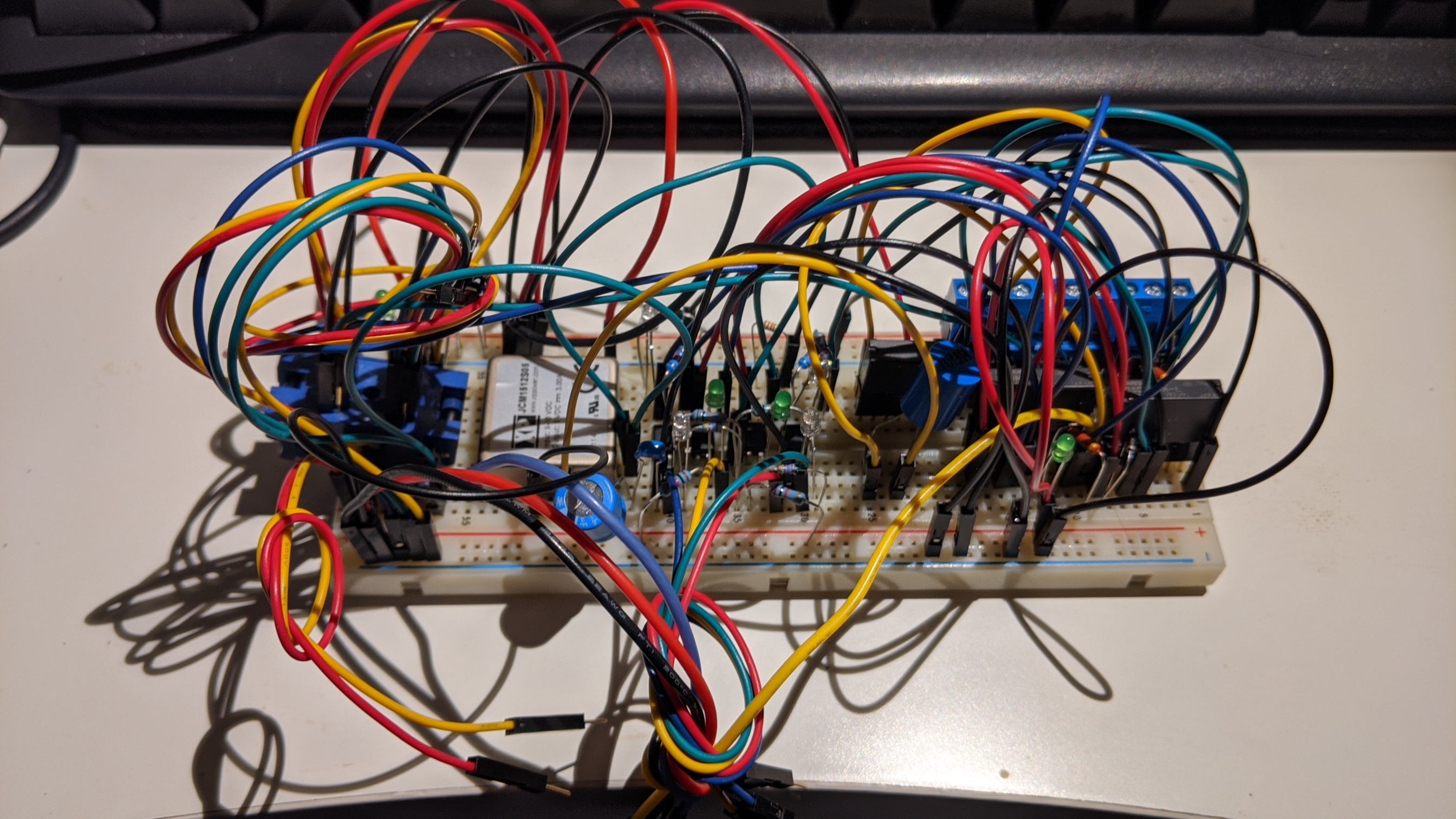
I've sent out for a set of 3 prototype boards which should be arriving in the next few days. I found 3 ADM3052 ICs (the least common component) and I've bought them to use with these three boards. From there I'm looking to build one out completely to test, and if it works I'm happy to sell the others to anyone that's considering installing this mod on their Focus.

If I'm doing my math right the rest of the board components, beyond the ADM3052 chips I've bought, would total about $45. There's some wiggle room particularly with pin header selections but that doesn't change it much. So, if anyone is interested in one of these 2 other boards, let me know and I can sell you one to use for yourself.

Just to keep numbers round, let's say $55 for a board with the ADM3052, you add your $45 in other components (I'll have a list up on the GitHub soon) and a $99 EVTV CANDue and you're got all the low voltage stuff ready to pair with a CHAdeMO port and contactors.

Obviously this is all contingent on validation of the one I build out and the ADM3052s won't be here for a few weeks. Stay tuned.

Re: Quick Charge Mod - CH4D3M0

Posted: Tue Apr 26, 2022 3:05 pm
by Anti_Climax
The boards have arrived

Image

Re: Quick Charge Mod - CH4D3M0

Posted: Sun May 01, 2022 10:02 am
by Anti_Climax
Still waiting on a few parts but almost all of it is ready to solder.

Image

Re: Quick Charge Mod - CH4D3M0

Posted: Sun May 01, 2022 12:44 pm
by Heima
This is so kool!

Re: Quick Charge Mod - CH4D3M0

Posted: Fri May 06, 2022 9:46 am
by Anti_Climax
At this point I have all components with the exception of the ADM3052 CAN Transceiver chips - but I just got confirmation they shipped out from Shenzhen. Not sure how long it will take them to get here but once they do, I can reflow the three SMD chips on the boards and then start hand soldering the rest.

Image

Unrelated to the CHAdeMO board itself; now that I have that CCS module it's apparent there are "bolted" bus connections inside it so anyone with a CCS enabled Focus has a more easily accessed point to tap in for a CHAdeMO port if they are so inclined, rather than opening the TCM and tying in there. They are located under the CCS control board so you couldn't really go in from the "back" but it would be possible to drill into the top, bottom or front to get directly to the bus bars.

Re: Quick Charge Mod - CH4D3M0

Posted: Thu May 26, 2022 9:17 am
by Anti_Climax
Soldered up the board and tested what I could. All joints seemed good. No smoke when I have it power. I did find out I used the wrong size resistor for an indicator LED I added.

Took it to run a test - no dice. The charger acted like nothing was plugged in. Started rechecking the schematic and found out I had misplaced a cap early on. Easy enough to modify the board with some green wire repair.

Ran another test, same deal. The Arduino is running and outputting serial monitoring data, so that's not a problem. Dug deeper into the schematic and found I also missed a 1K resistor, but that was REALLY easy to put into the system.

Tried again, still the same. At this point I'm going to need to dig pretty deep to see where this is stumbling.

Re: Quick Charge Mod - CH4D3M0

Posted: Mon Jun 13, 2022 6:49 pm
by Anti_Climax
Been a while, figured it was time for an update.

I've found various issues in the board as you expect with a first prototype, stuff missing, stuff that's wrong, stuff that wasn't caught in the original circuit mapping and errors that propagated through the chain.

At this point I've validated the basic mechanical functions of the board - it correctly reads inputs, can set outputs and trigger the relays. CAN bus traffic from the car is getting into the Arduino and output is writing to the correct pins, but it seems that the output from the ADM3052 is dead. I get CANBus data if I hotwire the original eval board into the system.

Not sure if the chip was damaged during soldering, fake/counterfeit or DOA. I'm going to take the chip off the eval board and try again. Then use the empty board to test the other chips and see if any of them work. I'll let you know how it goes.

Re: Quick Charge Mod - CH4D3M0

Posted: Thu Jun 16, 2022 5:51 pm
by Heima
yes, please do keep us posted

Re: Quick Charge Mod - CH4D3M0

Posted: Mon Jun 20, 2022 8:55 pm
by Anti_Climax
I'm going to order a new set of optocouplers along with all the various passives and start on a new board. Pretty sure I burned out one of the chips while testing. Haven't given up.

Re: Quick Charge Mod - CH4D3M0

Posted: Sun Jul 10, 2022 2:30 pm
by Anti_Climax
Alright, slow going. Since I was ordering a bunch more stuff - and since it's obvious my current boards would need rework to be usable at all - I figured I may as well start over with a breadboard version for validation.

The older circuit used some sparkfun optocouplers that I copied over as is, but was always sort of skeptical of. They were intended for 5v/3.3V isolation and were being used for 12V with some higher value resistors. Since at least one optocoupler seems to have failed (though possibly from heat), I went looking for a proper 12V/3.3V isolation circuit and found one to copy. Since I can decide if the logic will be inverted or not in software, I was able to omit a few components and simplify things along the way. The new version also uses through hole optocoupler chips, so the CANBus chip is the only surface mount component left.

In the process of integrating those changes I found out I had some output pins flipped. Not likely to smoke anything but I'm sure it didn't help things work. So add that to flipped CANBus lines, misrouted data lines, incorrect placement of components that turned out to be not needed at all and a few other things; I'm pretty much running out of ways to do it wrong.

So now I'm trying to build it up on the breadboard and see if it behaves correctly. If so, I'll see about doing another shield prototype. Might put the CANBus chip on a breakout to help with routing and future assembly too.