Coolant Change. Use forscan to get the air out?

Ford Focus Electric Forum

Help Support Ford Focus Electric Forum:

This site may earn a commission from merchant affiliate links, including eBay, Amazon, and others.

triangles

Well-known member
Joined
Aug 16, 2011
Messages
1,232
Location
Toledo, Ohio
I swear I saw this discussed somewhere on here but cannot find it. I thought you could command the coolant valves/pumps with Forscan. After doing a "warranty flush" on my coolant, I fumbled around with forscan trying to figure out where to command the pumps/diverter valves to purge the air.

Am I getting old and senile or just missing where to do this with forscan.

TIA
 
I think I saw there somewhere here as well. If you are desperate like I was, 2 of the loops will work themselves out because they have degass lines. The heater loop does not have a degass line, so you'd be stuck with air in that line without the ability to change the diverters to make one big loop.

I forget what I did to get the pumps to run...probably just turned the car on. I remember squeezing the coolant lines quickly to promote movement of the air bubbles. But anyway, you are right to just get it into one big loop with Forscan. If you figure it out outside of the forum, please post for an official record. :)
 
Not sure if this helps, but when I was in the process of removing my 1 speed geardrive/ motor assembly for replacement, if 12 Volt power is still connected and you open the driver side door, the water pumps will come on for a couple seconds to cycle coolant through the loop. It was a pretty neat way to drain remaining coolant out.
 
triangles said:
I swear I saw this discussed somewhere on here but cannot find it. I thought you could command the coolant valves/pumps with Forscan. After doing a "warranty flush" on my coolant, I fumbled around with forscan trying to figure out where to command the pumps/diverter valves to purge the air.

Am I getting old and senile or just missing where to do this with forscan.

TIA

It's not intuitive, but you can select to view certain modules and there's an option at the bottom that can be changed to control stuff. I don't have it in front of me right now, but if you look along the bottom of the data view you should find it.

The degas seems to be diverters set to the middle and pumps ramped up near full for a while.
 
1. Connect to the vehicle in Forscan.

2. Click the Oscilloscope button in the left column
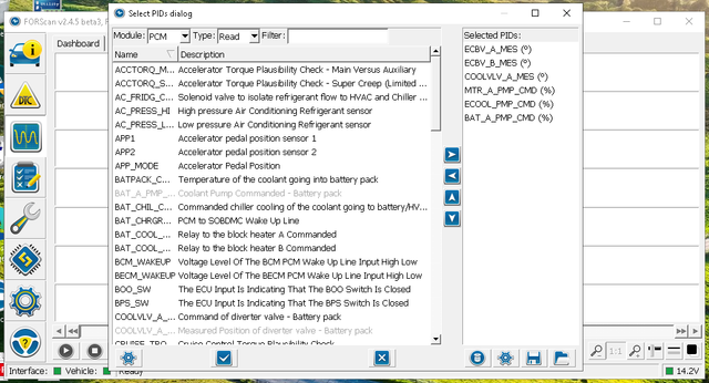
3. Click the small gear button at the bottom of the window.
4. Select PCM from the Module drop down.
5. Select the PIDs as seen in the photo.
6. Click the check mark button at the bottom of the window.

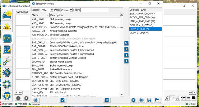
7. Click the small gear button at the bottom of the window.
8. Select PCM from the Module drop down.
9. Select Control from the Type drop down.
10. Select the PIDs as seen in the photo.
11. Click the check mark button at the bottom of the window.

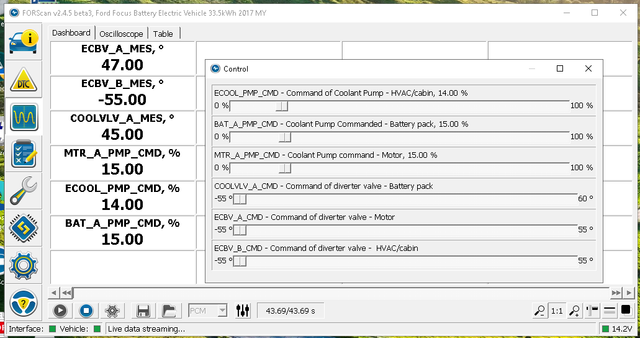
12. Click the Dashboard tab.
13. Click the blue play (right triangle) button at the bottom of the window.
14. Click the greyed out (X'ed out) vertical slider bars button at the bottom of the window.
15. In the control window that opens, set the horizontol sliders for the pump speeds and valve positions. After setting a value, there is a time delay to achieve the setting.
16. The dashboard will show what the actual speeds and positions are in real time.

NOTE: If you set a speed to 100% , you have a high probability of causing air entrapment and enrichment. This is because of the pressure drop across the degas lines will cause them to suck, rather than drain. Similarly if you set a valve all the way one way, with a moderate speed. So with all that in mind, try to set the valves to the 0 degrees (center position), and try to keep the pump speeds less than 75%.

The best way to get air out of the cooling system is to use a vacuum coolant bleeder. Using one of those and setting valves to 0 and pump speeds to 50% does a good enough job.

NOTE: Often the pump speeds will not return back to 0, even though you set the sliders to 0. You will have to power cycle the car to reset them back to normal.
 
Heima, Thanks for taking the time to post this with steps. I had gotten as far as your step 13 but couldn't figure out how to change any of the settings. I did a drain and fill on the radiator twice to serve as my "10 year - 150k mile coolant change even though I am just shy of 8 years in and less than 1/3 the miles. I was mostly curious to see the condition of the coolant that came out. Much as I expected it still looked new, although there was some white precipitate in the expansion reservoir. I should probably do something more like a complete drain and fill since I only changed about 6L and the manual says the capacity is 15L. Honestly though I expect my battery to be the death of my FFE before corrosion becomes an issue with the coolant.
 
Hiema, I too thank you for taking the time to post how to operate the pumps with forscan. I tried it out and was able to make all three of the pump function properly, but I am still getting DTC P2601 (pump "A" control module stuck/off) Do you have any suggestions what I might check on next? Thank you in advance. bb
 
Yes, you can also feel it and hear it struggling when you squeeze the hose.
 
Last edited:
Hiema, I too thank you for taking the time to post how to operate the pumps with forscan. I tried it out and was able to make all three of the pump function properly, but I am still getting DTC P2601 (pump "A" control module stuck/off) Do you have any suggestions what I might check on next? Thank you in advance. bb
So when you are monitoring the pumps, do they report a reasonable or appropriate %? When you change the %, do you see the % change after you move the slider? The service manual probably has some info about that DTC P2601. At first guess, I would think the pump's signal return is having some problem. Like the wire is making a poor connection somewhere.
 
So when you are monitoring the pumps, do they report a reasonable or appropriate %? When you change the %, do you see the % change after you move the slider? The service manual probably has some info about that DTC P2601. At first guess, I would think the pump's signal return is having some problem. Like the wire is making a poor connection somewhere.
Thank you for your response. Yes the pumps do report the appropriate % response when being adjusted. Your guess that the pump return signal is a possible suspect is a good suggestion. I’ll start with inspection of the wires from the pump to the PCM and see if any of them are suspect or have to much resistance. I have downloaded the service manual and will check it for anything related to code P2601 however at first glance the manual seems hard to negotiate.
 
So I am looking at the service manual, and I cannot find a P2601 at all, however, there is this:
P0CC1:00Drive Motor "A" Coolant Pump Control Circuit/OpenCLEAR the DTC . RERUN the KOEO self-test. If the DTC returns, GO to Pinpoint Test O
P0CC2:00Drive Motor "A" Coolant Pump Control Circuit Range/PerformanceCLEAR the DTC . RERUN the KOEO self-test. If the DTC returns, GO to Pinpoint Test O
P0CC2:12Drive Motor "A" Coolant Pump Control Circuit Range/Performance Short To BatteryCLEAR the DTC . RERUN the KOEO self-test. If the DTC returns, GO to Pinpoint Test O
P0CC2:14Drive Motor "A" Coolant Pump Control Circuit Range/Performance Short To Ground or OpenCLEAR the DTC . RERUN the KOEO self-test. If the DTC returns, GO to Pinpoint Test O
It seems the P0CC2 has almost the same description of your DTC according to Forscan:
Code: P2601-Coolant Pump Control Circuit Range/Performance.

So its long, but here is Pinpoint Test O:
PINPOINT TEST O : P0CC1:00, P0CC2:00, P0CC2:12, P0CC2:14
O1 RETRIEVE AND RECORD ALL DTCS
  • Connect the diagnostic tool.
  • Using the scan tool, retrieve all Diagnostic Trouble Codes (DTCs).
Is DTC P0CC1:00, P0CC2:00, P0CC2:12 and/or P0CC2:14 set?

Yes
For Diagnostic Trouble Codes (DTCs) P0CC1:00 and P0CC2:00, GO to O2 For DTC P0CC2:12, GO to O7 For DTC P0CC2:14, GO to O8
No
GO to Symptom Chart.​
O2 CHECK THE DRIVE MOTOR COOLANT PUMP POWER CIRCUIT
  • Ignition OFF.
  • Disconnect Drive Motor Coolant Pump C1812 .
  • Ignition ON.
  • Measure the voltage between.


    Positive LeadMeasurement / ActionNegative Lead
    C1812-1
    e141493_eur_99.jpg
    Ground
    C1812-5
    e141493_eur_99.jpg
    Ground
Are the voltages greater than 10.5 volts?

Yes
GO to O3
No
REPAIR the affected circuit(s).​
O3 CHECK THE DRIVE MOTOR COOLANT PUMP GROUND CIRCUIT FOR AN OPEN
  • Measure the voltage between.


    Positive LeadMeasurement / ActionNegative Lead
    C1812-1
    e141493_eur_99.jpg
    C1812-4
Is voltage greater than 10.5 volts?

Yes
GO to O4
No
REPAIR the circuit.​
O4 CHECK THE DRIVE MOTOR COOLANT PUMP PULSE WIDTH MODULATION (PWM) CIRCUIT FOR AN OPEN
  • Ignition OFF.
  • Disconnect Powertrain Control Module (PCM) C175B .
  • Measure the resistance between.


    Positive LeadMeasurement / ActionNegative Lead
    C175B-13
    e141499_eur_99.jpg
    C1812-3
Is the resistance less than 5.0 ohms?

Yes
GO to O5
No
REPAIR the circuit.​
O5 CHECK THE DRIVE MOTOR COOLANT PUMP PULSE WIDTH MODULATION (PWM) CIRCUIT FOR A SHORT TO GROUND
  • Measure the resistance between.


    Positive LeadMeasurement / ActionNegative Lead
    C175B-13
    e141499_eur_99.jpg
    Ground
Is the resistance greater than 10,000 ohms?

Yes
GO to O6
No
REPAIR the circuit.​
O6 CHECK THE DRIVE MOTOR COOLANT PUMP PULSE WIDTH MODULATION (PWM) CIRCUIT FOR A SHORT TO POWER
  • Ignition ON.
  • Measure the voltage between.


    Positive LeadMeasurement / ActionNegative Lead
    C175B-13
    e141493_eur_99.jpg
    Ground
Is voltage greater than 0.1 volt?

Yes
REPAIR the circuit.​
No
INSTALL a new electric motor coolant pump.
REFER to: Electric Motor Coolant Pump (303-03 Electric Powertrain Cooling, Removal and Installation).​
O7 CHECK THE DRIVE MOTOR COOLANT PUMP DIAGNOSTIC CIRCUIT FOR A SHORT TO POWER
  • Ignition OFF.
  • Disconnect Powertrain Control Module (PCM) C175B .
  • Disconnect Drive Motor Coolant Pump C1812 .
  • Ignition ON.
  • Measure the voltage between.


    Positive LeadMeasurement / ActionNegative Lead
    C175B-51
    e141493_eur_99.jpg
    Ground
Is voltage greater than 0.1 volt?

Yes
REPAIR the circuit.​
No
INSTALL a new PCM .
REFER to: Powertrain Control Module (PCM) (303-14 Electric Powertrain Control, Removal and Installation).​
O8 CHECK THE DRIVE MOTOR COOLANT PUMP DIAGNOSTIC CIRCUIT FOR AN OPEN
  • Ignition OFF.
  • Disconnect Powertrain Control Module (PCM) C175B .
  • Disconnect Drive Motor Coolant Pump C1812 .
  • Measure the resistance between.


    Positive LeadMeasurement / ActionNegative Lead
    C175B-51
    e141499_eur_99.jpg
    C1812-2
Is the resistance less than 5.0 ohms?

Yes
GO to O9
No
REPAIR the circuit.​
O9 CHECK THE DRIVE MOTOR COOLANT PUMP DIAGNOSTIC CIRCUIT FOR A SHORT TO GROUND
  • Measure the resistance between.


    Positive LeadMeasurement / ActionNegative Lead
    C175B-51
    e141499_eur_99.jpg
    Ground
Is the resistance greater than 10,000 ohms?

Yes
INSTALL a new PCM .
REFER to: Powertrain Control Module (PCM) (303-14 Electric Powertrain Control, Removal and Installation).​
No
REPAIR the circuit.​

So this all checks for continuity and power to and from the pump. If you have an oscilloscope to check the PWM, that would help. Alternatively, if you find something up with the pump, you could try swapping with another, and seeing if the DTC moves to that location.
 
Looking at the wiring diagram manual, it states that C1812 is for the cabin heater coolant pump, and C1813 is the electric motor coolant pump. The pinouts are the same. There are 4 pins, not 5 as alluded above.
Pin 1 and 2 are next to the little catch to secure the connector, pins 3 and 4 are the other two.
Pin 1 carries positive 12v is grey and yellow
Pin 2 carries ground is black and green
Pin 3 carries the signal to the pump is yellow and green (C1812) or black and blue (C1813)
Pin 4 carries the return to the PCM is blue and orange (C1812) or blue and grey (C1813)

C175B is the 95 pin connector on the PCM.
Pin 11 is black and blue, and provides the signal to C1813
Pin 13 is yellow and green, and provides the signal to C1812.
Pin 51 is blue and orange, and receives the feedback from C1812
Pin 53 is blue and grey, and receives the feedback from C1813
 
Just a curiosity, but has anyone reviewed the service manual for these to see if there's a specific procedure Ford has already programmed for this? I know on my C-Max in its service manual there's a special procedure involving some 'pedal dance' shenanigans to allow it to cycle coolant through and bleed the system. It opens up all the diverter valves, runs the ICE at a solid 2k rpm (getting the thermostat open), and runs the electric coolant pump at full speed (or what they consider 'full speed'). I'd be surprised if the Focus Electric with its unique cooling loops that there's isn't something similar programmed in.
 
That would be cool, but I do not remember seeing anything like that in the service manual. I remember something like that in the Mitsubishi Imiev service manual. I am curious if the C-Max process would work for the FFE.

And now I have to stop myself, because the C-Max does not have a coolant system for its HV battery, and so it has a much simpler coolant path to bleed.

In fact, does any hybrid vehicle have a liquid cooled HV battery?
 
Found this:
Fill mode Step by step instruction:
1.Turn the key on or, if equipped, press the START button.Transmission in park.Climate control system off.
2.Enter system fill mode:
Press the brake pedal for 10 seconds, release.
Press the accelerator pedal to 100% for 10 seconds.
3. Hold the accelerator pedal to 100% for 1 minute. The coolant pump will operate at 100% and the engine will operate at 2,000 RPM.
4. Check the coolant level and fill to degas bottle MAX line. Check if the thermostat is open (lower radiator hose is hot).
5. Hold the accelerator pedal to 100% for 5 minutes. The coolant pump will operate at 100% and the engine will operate at 2,000 RPM.
6. Check the coolant level and fill to degas bottle MAX line. Check if the thermostat is open (lower radiator hose is hot).
7. Repeat steps 6 and 7 until the thermostat is open (lower radiator hose is hot).
8. Hold the accelerator pedal to 100% for 5 minutes. The coolant pump will operate at 100% and the engine will operate at 2,000 RPM.
9. Check the coolant level and if necessary fill to degas bottle MAX line.
10.For vehicles filled with the Vacuum System Filler:
Repeat steps 8 and 9 until a total of 20 minutes elapse after the thermostat opens.
For vehicles filled without the Vacuum System Filler:
Repeat steps 8 and 9 until a total of 20 minutes elapse after either the thermostat opens or the coolant level stabilizes, whichever is longer.
11. Check the coolant level and fill to degas bottle MAX line.

So, the step to wait for it to heat up, well..... gonna be waiting a while.
I guess a brick could be used to hold the accelerator for the later steps.

Anyone game to try this?
 
Back
Top