CCS upgrade for older Focus

Ford Focus Electric Forum

Help Support Ford Focus Electric Forum:

This site may earn a commission from merchant affiliate links, including eBay, Amazon, and others.

Anti_Climax

Well-known member
Joined
May 20, 2016
Messages
579
Location
The Valley of the Sun
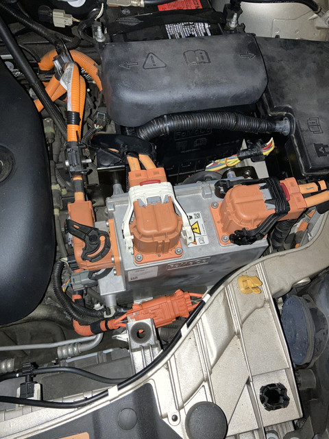
I've been comparing the diagrams for the later model Focus with fast charging and the earlier models without.

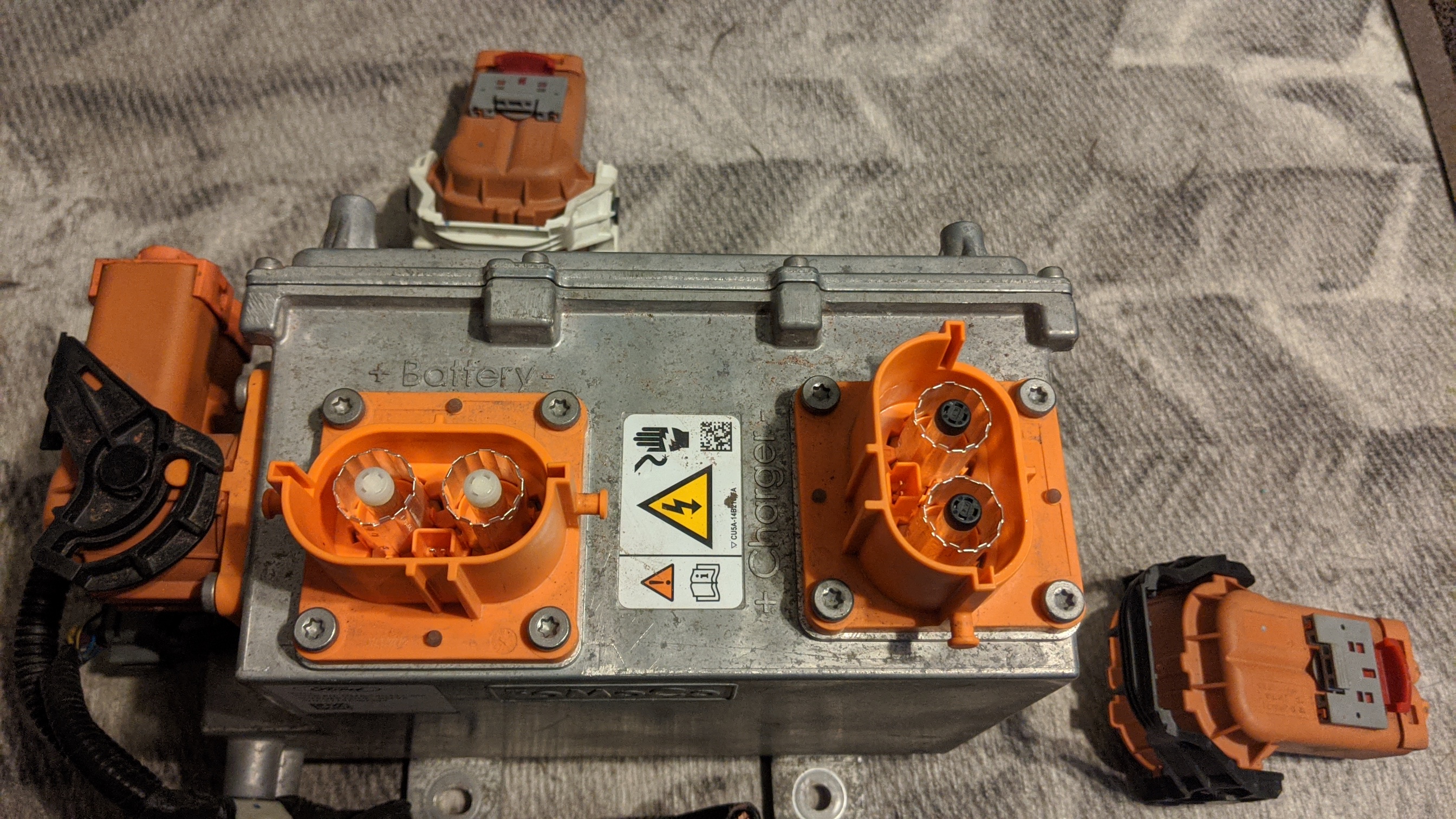
It seems the differences are few but significant - aside from the different port/fender and what they simply label as a "module", the entire HV harness running to the battery has to be swapped. The actual connection to the battery and charger is the same but the newer harness has additional connectors to support the additional high voltage wiring into the system.

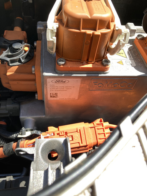
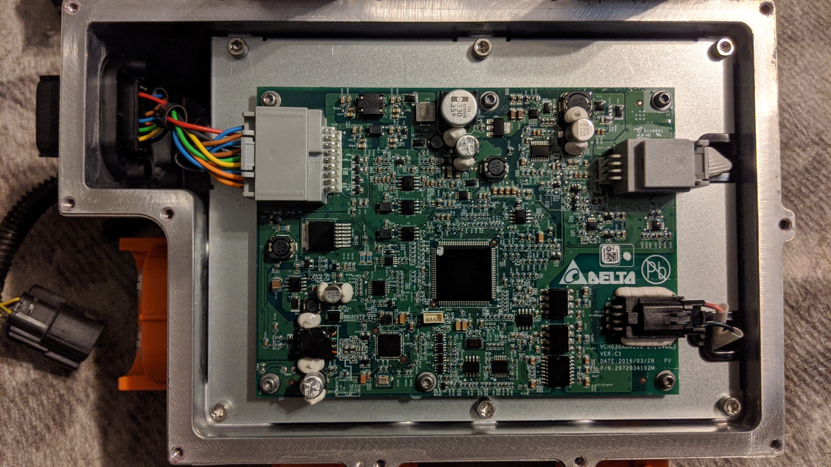
It seems that the on board charger itself is abstracted from the process and might not need to be changed, but I am curious about this "module". Does anyone have any further details on it? While they aren't cheap from the manufacturer, I'm seriously considering trying to get ahold of these parts to try and install CCS in my 2012.
 
Do you mean what I call a front junction box?
I believe it has some contactors inside, it cables to the DC fast charge terminals, the inverter, and the HV battery.
There is also some logic harness attached, probably for control of the contactors and possibly protocol.

In this picture, the HV cable on the right is labeled "Charger" and goes to the DC FC terminals of the charge port. The HV cable in the middle is labeled "Battery". The HV cable on the left is labeled "ISC" and goes to the inverter. The black and grey connectors underneath are labeled "Signal".
The J1772 HV cable is in front of the module.
 
Here is the part label.

photo url
The part number is H1F8-14G431-AJ

In checking with Forscan, in the configuration for my 2017, this appears for that part number:

GFM2 - Generic Function Module 2
Part number: H1F8-14G431-AJ
Calibration level: H1F8-14G431-AJ (latest known: H1F8-14G431-AM)
Strategy : H1F8-14G525-AJ
Total Distance: 15216.1 miles

Forscan can reset, self-test, and display live data for the GFM2 module.
However, it cannot configure or directly display configuration data for the module.
 
With that info, I bit the bullet and bought one from eBay. Going to see if I can hack it into my existing system. Since I have a tap into the battery bus already I could technically splice into what I have rather than replacing the whole HV harness.

I have the shop manual for the pre-2017 models, did a later version ever make the rounds?
 
My module came in yesterday. The listing noted it as a DC/DC converter, though it is for certain that CCS interface module. For the sake of clarity, the manuals note it being "Generic Function Module 2" as there is another Generic Function Module that is tied to the charging port itself - managing the ring mostly. The module has a label calling it "EVCC" so I'll probably adopt that as a name.

It has one HV connector that goes "to the battery" and another that says it goes to "ISC", which really is just connecting to the TCM area of the HV DC harness. The last HV connector goes to the fat pins of the CCS port and there are 2 harness connectors that carry CANBus, power, etc in and out of the module. It interfaces with the original GFM to pass PLC/Pilot, control the port interlock, etc.

I opened it up and found a MC9S12XEP100 based board made by Delta (likely the whole EVCC http://www.evat.or.th/attachments/view/?attach_id=216475). Under that is the good stuff. The ISC and Battery connections are hard bussed together, so even if the thing is totally dead, the rest of the system would be able to operate normally. The charger pins are run through HV contactors which are controlled by the board above. This is effectively the same arrangement as the CHAdeMO hack - a tap into the HVDC bus where external charger current can be connected via contactors.

There are still some open questions about how this will work. Since my GFM is the original J1772 version, it will almost certainly not be able to respond correctly to commands sent by the EVCC. If I can find one I might put it to use, but in the meantime I have a new Arduino Due that could be a gateway to the GFM - intercepting commands it wouldn't otherwise understand and reply on it's behalf with correct data. This Due would probably operate the interlock circuit on the CCS port I install.

Other than that, there's just the potential that this will simply be unable to work with the other components in my older car - but there is the distinct possibility that it could be a nearly seamless drop in. Only time will tell at this point. Should it be the former, I may still be able to use this hardware in a more isolated way, using the Due to make it think the rest of the car is playing along and have it operate while the car is started, like the current CHAdeMO hardware.

0UvyYIh.jpg


j9c3lLw.jpg


9cF35t6.jpg


t6JotXA.jpg


0i8nLwH.jpg
 
I've dug in a bit over the day and traced all the wiring inside this EVCC. One of the most interesting things is that it has a second CANBus interface on it that wires to the low voltage connectors but says it's "not used" in the vehicle wiring diagrams. It's possible this is a separate bus for manufacturer diagnostics but there's also the remote possibility that this module is more generic and actually has support for CHAdeMO. How awesome would it be for any CCS focus to be able to add a CHAdeMO port? I'll definitely be poking at that.

Other than that, the wiring for this is pretty simple. There are 24 pins in the connectors but only 18 are used. 4 are CANBus, 4 are locking solenoid interface, 4 are for thermistors, power, ground, pilot in/out and 2 for the HV interlock circuit. I still need to get a port but I really feel like there isn't anything special happening with the rest of the car. Here's hoping.
 
At this point, the largest open questions relate to the specs of the CCS port. There are 2 thermistors (one under the AC plug and one under the DC plug), wires that control the lock actuator and wires that provide feedback on the lock state. At this point I don't know the specs on the latch hardware or the thermistors.

If anyone is feeling adventurous, some multi-meter readings from some pins would be very helpful. If you're looking at the side of the module with the two 12 wire connectors, the lower one connects to the port wiring. The pins number from top rear to bottom front.

Pins 1 and 2 (top rear) are the AC port thermistor, 5 and 6 (top front) are the DC port thermistor, 9 and 10 (bottom middle) are the latch control and 11 and 12 (bottom front) are latch sense.

If I can get a resistance reading for pins 1/2 and 5/6 (along with a ball park on the port temp), I can at least figure out what type of thermistor is getting used. Continuity on 9/10 and 11/12 would give me an idea of the idle state and - if at all possible - voltage readings and continuity on those pins while the CCS latch is engaged, I can potentially figure out what type of solenoid is being used. My guess is it's a 12V solenoid, possibly latching, and the sense is most likely a switch that is open or closed depending on the latch position.

With the exception of the live solenoid stuff, these readings can be pulled by unplugging the connector and probing the contacts on the cable itself instead of trying to touch them in place.

Any takers?

EDIT: I was able to look through the data sheet for a Phoenix Contacts CCS port and got some very useful data. At least for that model, it is a 12V solenoid that moves one way with a sufficient duration of positive voltage and moves back with reversed polarity. The sense pin changes impedance from 1K while open to 11K while closed. The temp sensors are PTC thermistor arrays calibrated to a "Pt 1000 characteristic curve at an ambient temperature of 25°C"

So, really, it's mostly a matter of confirming if the Ford CCS port runs on the same standards.
 
CCS plug is on it's way. Finally figured out why the CCS harness looks so weird in component views and diagrams - I thought they had spliced in an additional socket on the harness and in reality they took the end that was going to the TCM and routed it to the EVCC with a variant of the same connector, while the diagram lumps the short interconnect cable that goes from the EVCC to the TCM on top of what's there.

So, it looked weird because it was actually 2 cables.

Setup-wise we have the harness coming from the battery. It splits to the DC side of the Charger (SOBDM), continues up to the TCM on the pre-CCS (with a stright connector) or to the EVCC on the CCS models (with a right angle connector) and then completes the run to the TCM with another right angle and straight cable that's like 18-24" long. On the pre-CCS version, all the wires from the J1772 port go to the AC side of the Charger (SOBDM) while on the CCS, all the AC wiring still goes there, but the pilot line routes through the EVCC along the way. On the CCS model a separate harness runs from the EVCC to the low voltage CCS wiring for the latch, sense and thermistors. The DC pins route separate from all that to the EVCC. And then the EVCC is connected into power, ground, HVIL and canbus.

If a pre-CCS owner was willing to change the plug on their existing harness (or make a short adapter) and buy another to go from the EVCC to their TCM, it would be possible to physically set this up on any model year of focus. Looking forward to doing actual testing to see how much trouble the rest of the car gives me :/
 
Sorry to hear that, considering the part probably came from China, you are in for a wait.
 
Let me know how are you doing with the CCS fast charging,
I want to make such a port on my focus electric
only I will not do it using original details from the 2017 Focus Electric
Is it problematic to keep the car in a state with closed contactors, as in your project
https://github.com/truss-cpi/FFE-CHAdeMO.git
 
Back
Top