Anti_Climax
Well-known member
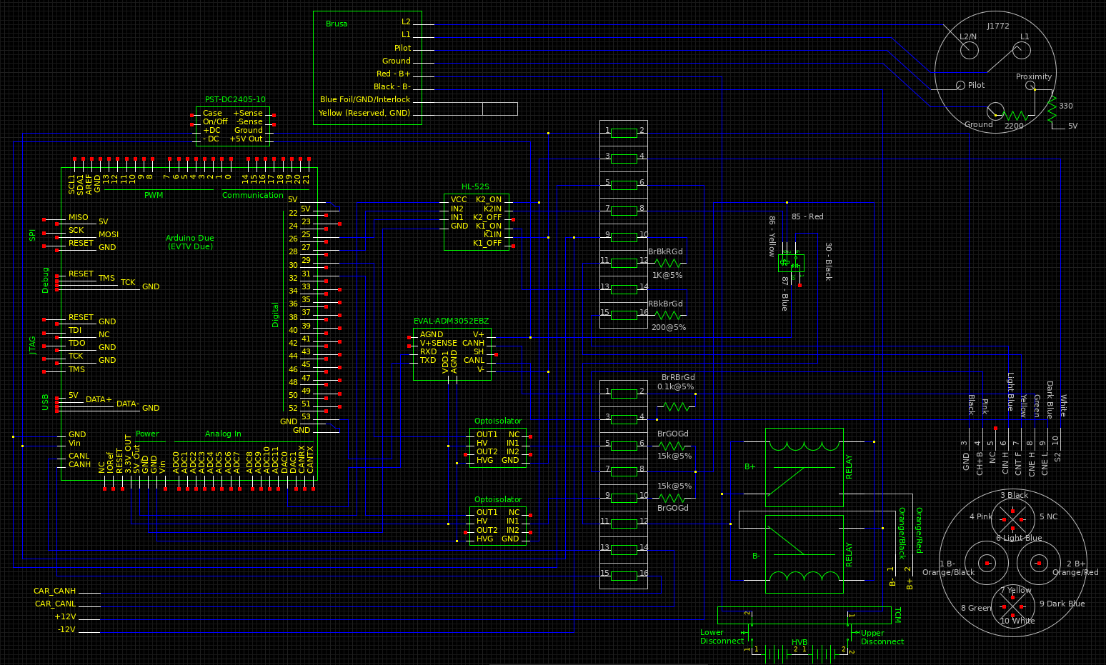
I've been going slow with setting up Sefs' CHAdeMO hardware on my Focus. I pulled apart the electronics and diagrammed everything up for reference as I went.
I started with this:
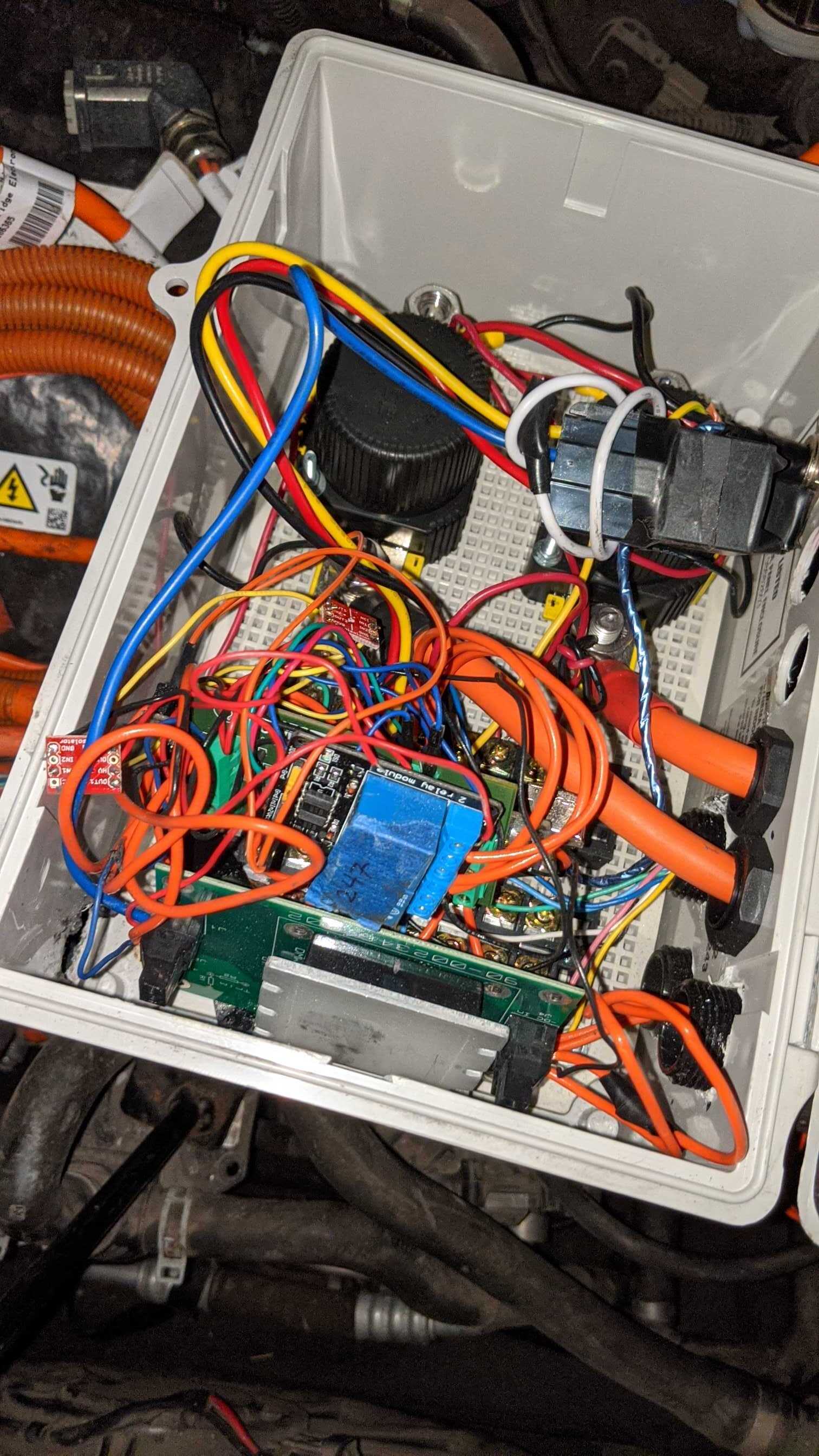
And got to this:
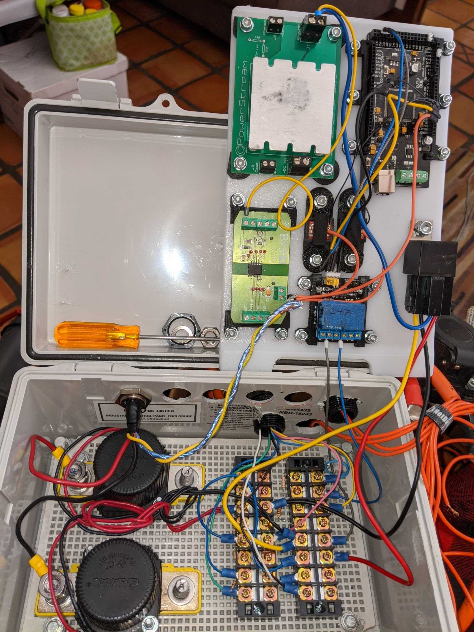
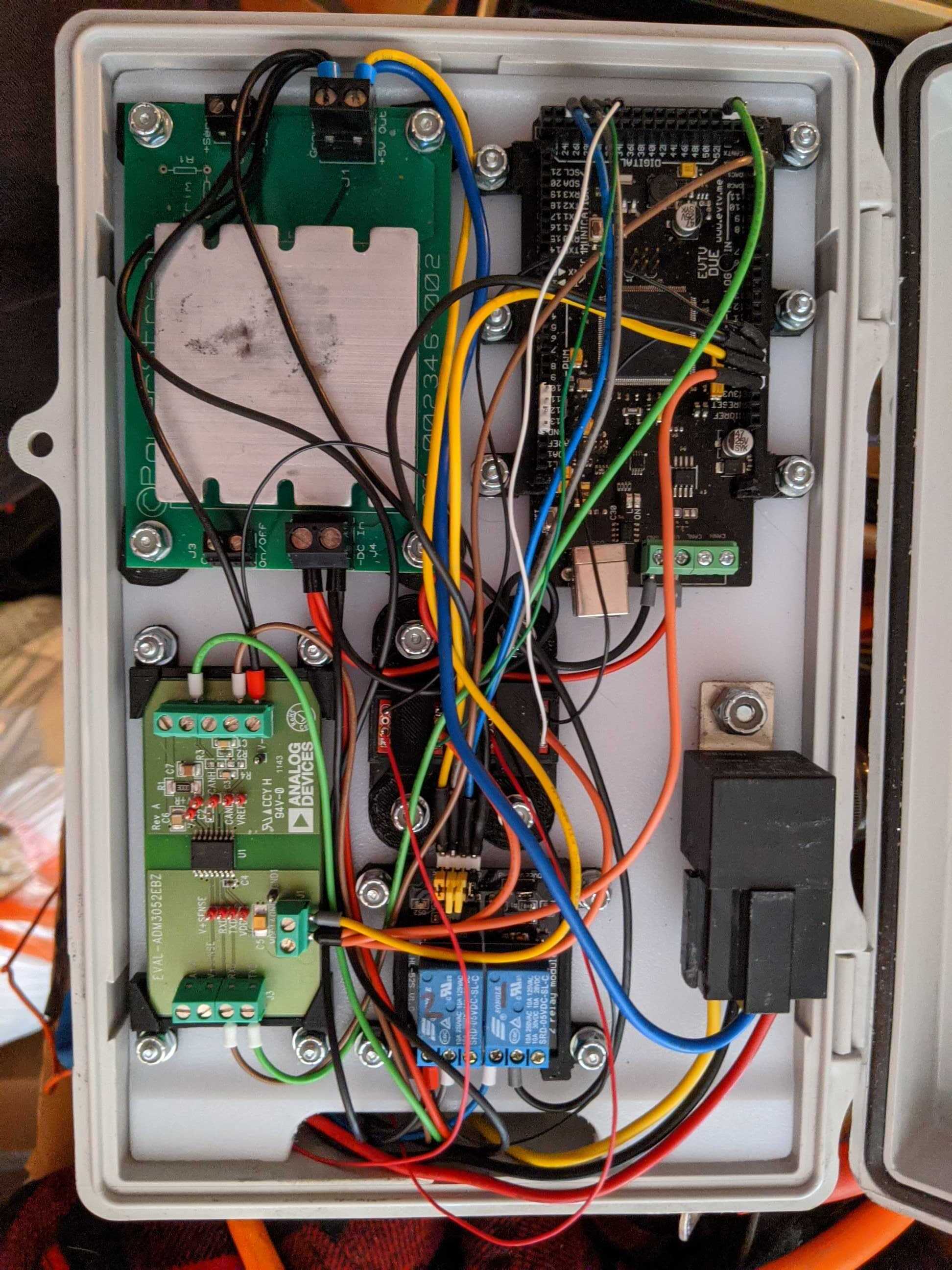
I then re-wired everything in a bit more permanent manner
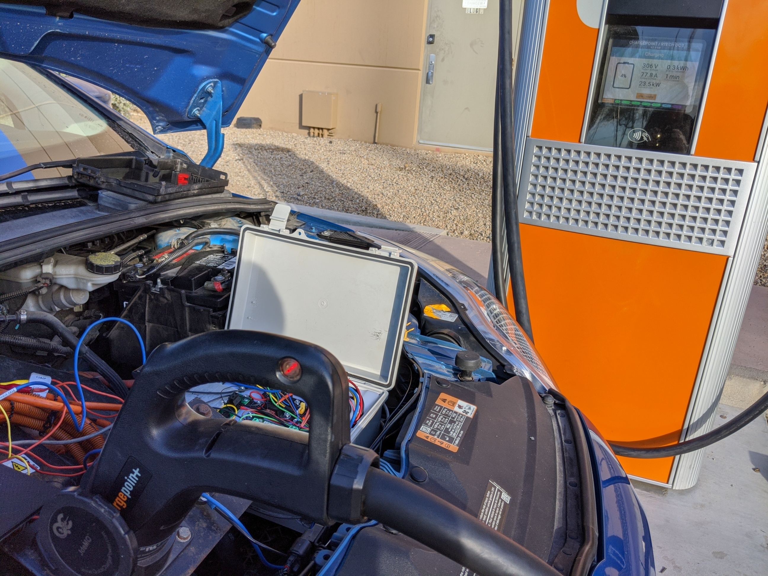
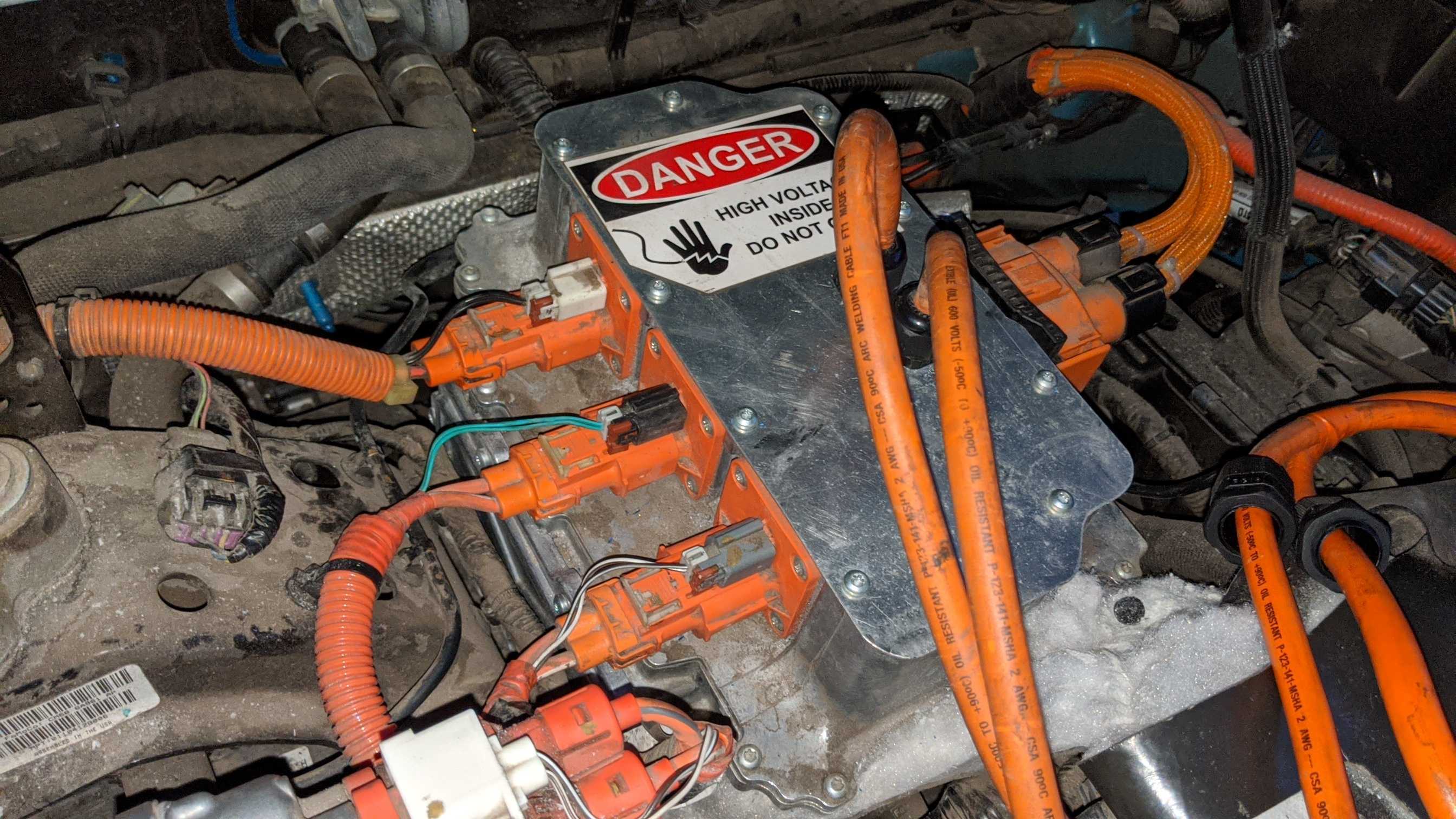
And installed it under the hood
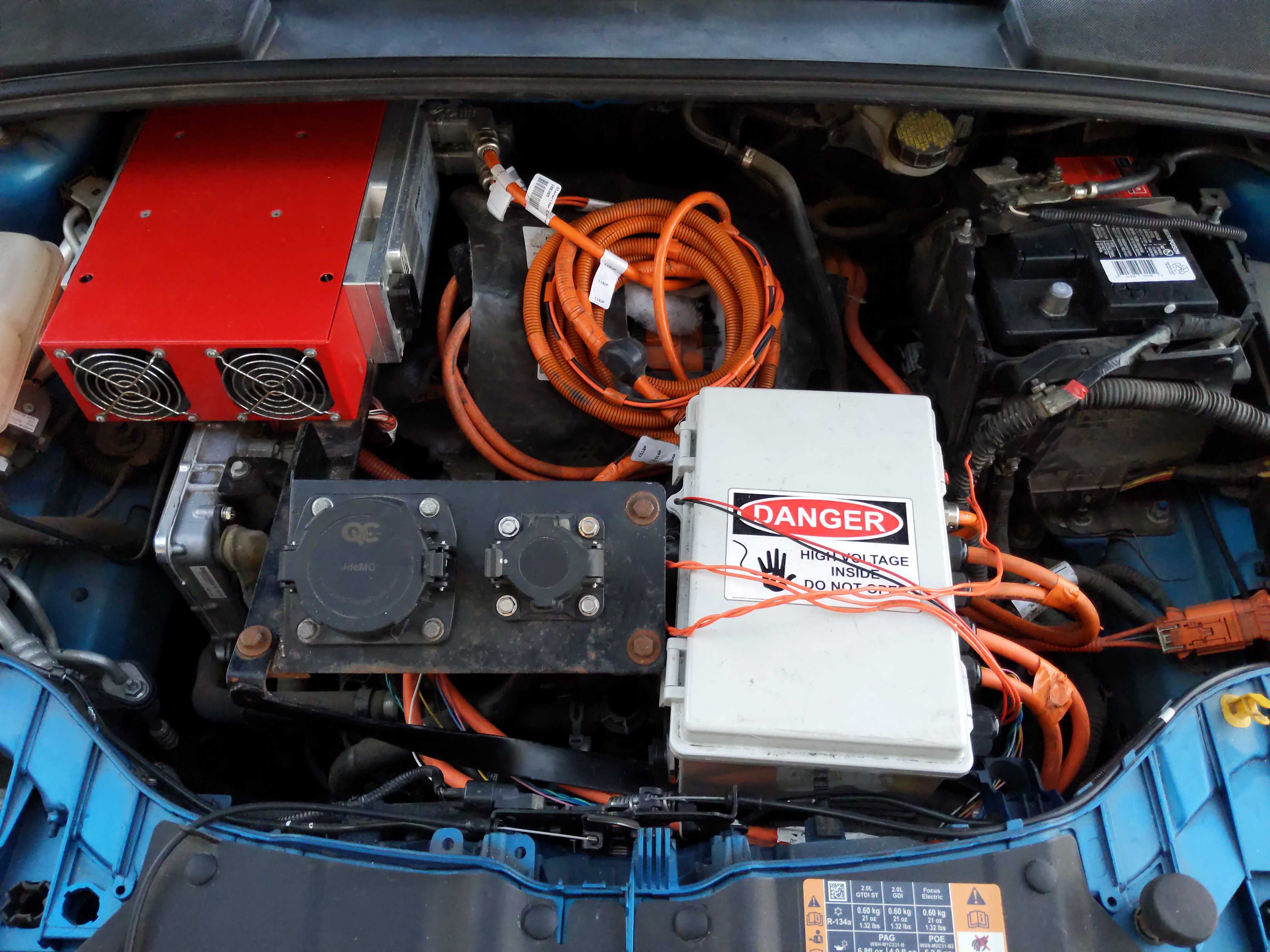
At this point, everything but the car side CAN Bus and 12V DC connections have been made. I reconnected the HVDC battery and 12V and the car came back on without any errors or warnings. I should have it ready to test by the end of this weekend. Figure I'll take it to the office and try it on the ChargePoint Express 250 we have there.
I started with this:
And got to this:
I then re-wired everything in a bit more permanent manner
And installed it under the hood
At this point, everything but the car side CAN Bus and 12V DC connections have been made. I reconnected the HVDC battery and 12V and the car came back on without any errors or warnings. I should have it ready to test by the end of this weekend. Figure I'll take it to the office and try it on the ChargePoint Express 250 we have there.